Aiming at the problems existing in the traditional pump control mode, a multi-loop intelligent water pump controller is designed, which has various control modes such as on-site manual control, background remote control and automatic control.
Huang Hai 1 Ren Jie 2 Lu Weiqing 2
(1. Architectural Design Institute of China Construction Third Bureau Group Co., Ltd., Wuhan 430064; 2. Ankerui Electric Co., Ltd., Shanghai 201801)
Abstract: In view of the problems existing in the traditional pump control mode, a multi-loop intelligent water pump controller is designed, which has various control modes such as on-site manual control, background remote control and automatic control.
Keywords: water pump controller water supply/drainage manual/level automatic control
Abstract:According to the construction and factory water supply and drainage application, the paper puts forward a multi loop smart pump controller, the controller requires control of water supply and drainage equipment can replace the traditional manual control, withthe scene in a variety of ways, The background of remote control and automatic control of liquid level, and on / emergence of the pump is running under voltage, over / underload (dry), protective effect of phase failure and external failures, also has the function of communication can pump operation information Uploaded to the industrial automation DCS system and the building of intelligent BA system.
Keywords: water supply and drainage pump controller / manual / automatic control of liquid level
0 Preface
In production automation and buildings, there are a large number of fans and pumps. For cost reasons, buttons, thermal relays, etc. are commonly used as control protection components. The thermal relay itself has design defects, poor repeatability, low reliability, and hidden dangers, and the traditional pump control method has the defects of complicated control circuit, single function, and difficult maintenance in the later stage. Therefore, the traditional pump control obviously cannot meet the functional requirements of informationization and intelligence. With the development of microcontrollers, the maturity of measurement protection technology has also changed the way traditional water pumps are used, from button indicators to the current integrated intelligent controllers.
1 Intelligent pump controller function
The functions required by the intelligent controller are: voltage, current, liquid level (switch or analog) measurement function; over/under voltage, phase sequence, overload, underload (dry run), break equal protection function; manual / Liquid level control function; alarm function of pump running fault and liquid level abnormality; management function of pump running information; communication function with upper computer system.
1.1 master chip
The MCU chip uses the 32-bit processor MCF51EM256 of Freescale's Coldfire-V1 (with hardware multiply-accumulate MAC unit) architecture core, with a clock frequency up to 50.33MHz, built-in 256K Flash, 16K RAM, 3-way timer, 3-way SCI communication interface, built-in RTC clock, I2C, SPI, KBI interface and other resources, on-chip integration with programmable delay module PDB and four 16-bit SAR ADC, PDB can directly control the sampling of the trigger ADC, complete the high precision The voltage and current AC sampling and liquid level measurement, the measurement accuracy can reach 0.5, and has a very high cost performance.
1.2 Voltage, current, liquid level signal acquisition circuit
The voltage acquisition circuit is shown in Figure 1. The three-phase voltages Ua, Ub, and Uc adopt a resistance step-down method, and add a boost voltage VREF to the sampling signal, so that the amplitude of the AC signal is greater than zero, which is convenient for AD sampling. At the output of the circuit, a voltage limiting diode is added to the AD input of the MCU chip to limit the input voltage to less than (clamping voltage) 3.3V, which can protect the AD sampling channel of the MCU chip.
.jpg)
Figure 1 voltage acquisition circuit
The general acquisition circuit of the liquid level signal is shown in Figure 2. When the liquid level sensor is a two-wire 4-20 mA interface, our controller is required to output a 24 VDC power supply and install resistors R22 and R45. When the liquid level sensor is a three-wire 4-20 mA interface, the sensor supply is provided by an external switching power supply, and resistors R44 and R45 are mounted. When the level sensor is 0-10V, install resistors R44 (0Ω) and R45. Similarly, a protection circuit should be added to the liquid level acquisition channel.
.jpg)
Figure 2 liquid level signal acquisition circuit
2 Traditional pump control method
In the traditional control circuit of the water pump, the main circuit is usually composed of a circuit breaker, a contactor and a thermal relay; the control circuit is generally composed of an indicator light, a meter, a control button, a transfer switch, a thermal relay, and a time relay. The traditional internal control of the pump control method is complicated, which makes it difficult for the maintenance personnel to debug the equipment and find the wrong wiring. The function is generally single, and the intelligent transformation cannot access the system, which increases the investment of the subsequent equipment.
The intelligent water pump controller integrates the electrical components required for pump control, including voltage and current display, multi-function protection relay, hand/automatic transfer switch, start/stop button, water level and pump status indication, and face cabinet installation. In the automatic mode of water supply/drainage, the two pumps alternately and alternately. According to the different water level, the control mode supports one water pump in the middle water level, and the two water pumps in the high (low) water level operate at the same time. The current protection supports independent on/off setting, and supports the standby pump to alarm only without tripping, and meets the application of fire places such as underground garages and fire hydrants. The secondary wiring diagram of the intelligent water pump controller is shown in Figure 3. Compared with the traditional way, it has the advantages of simple wiring, powerful function, and convenient upgrade in the later stage.
.jpg)
Figure 3 Intelligent pump controller one with a full-pressure starting liquid level controller control circuit diagram
4 performance comparison
The intelligent controller can effectively solve the problems of low safety and reliability of the traditional water pump control, large size of the control box, high energy consumption, low intelligence, and difficult upgrade. The performance of the traditional control box and the intelligent water pump control box are shown in Table 1.
Table 1 Comparison of control methods of traditional control box and intelligent water pump control box
Technical performance index | Traditional pump control box | Intelligent water pump control box | compare results |
voltage | AC187~231V | AC85V~265V/ DC100V~350V | The voltage usage range is significantly increased |
Overall energy consumption | 50W or more | Around 7W | Energy consumption reduced by 86% |
Wiring contact | 180 points | 41 points | Contact reduced by 77% |
Secondary line | 120m | 30m | Save the secondary line 70% |
Insulation resistance | 1MΩ or more | 100MΩ | Insulation safety enhancement |
Occupied volume | Distributed installation, large volume | Centralized installation, small footprint | Reduced cabinet size by approximately 30% |
Vibration resistance | —— | Can withstand the class I vibration response and endurance test specified in GB/T 11287-2000 | —— |
Anti-interference | —— | Can withstand Class III interference specified in GB/T 17626.2 to GB/T 17626.6 | —— |
Environmental adaptability | —— | Pollution level 3 | —— |
5 applications
Due to water seepage or rainfall, subways, underground stations or bridge tunnels cause a large amount of stagnant water, which seriously affects the work and normal travel of people, and requires regular or irregular drainage. Requirement: Two sewage pumps realize the discharge treatment of the cistern water; two sewage pumps alternately drain to prevent rusting; when the current working sewage pump fails, the standby pump can automatically input; When the water level is running, one water pump runs. When the water level is high, the two water pumps run at the same time. When the water collection tank is at the high water level, the water level alarms; it has low water level, medium water level, high water level, alarm and fault indicator. According to the requirements, the installation method of the liquid level control of the two pumps is designed, as shown in Figure 4.
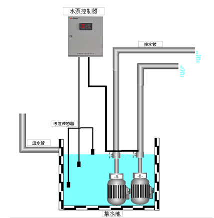
Figure 4 Installation method of liquid level control of two pumps
6 Conclusion
The intelligent pump controller is the core of the pump control management system to replace the traditional or PLC scheme control scheme, to achieve unattended automatic water supply / drainage function, and has a wealth of protection functions to make the pump run safer.
Article source: "Electrical Applications" No. 2, 2015
references
[1] GB50015-2003 Building Water Supply and Drainage Design Specification [S]
[2] JGJ16-2008 Civil Building Electrical Design Specification [S]
[3] Du Yiwei, Yan Houwei, Jin Dan. New motor control module technology and application [J]. Building Electric, 2011, (06).
[4] Jia Guofang. Research on online intelligent monitoring technology of water pump[J]. Drainage and Irrigation Machinery.2005(06).
Technical support: Yang Junjun, contact phone, mobile phone, QQ
Http://news.chinawj.com.cn Editor: (Hardware Business Network Information Center) http://news.chinawj.com.cn
Biomass Power Project is a kind of renewable resources power generation using biomass for power generation. Biomass Power generation includes agricultural and forestry Waste Gasification power system, waste incineration power generation, Biomass Gasification power generation and so on. Our company's main research and development technology is biomass gasification power generation. Biomass gasification for power generation is the conversion of biomass into combustible gas in a gasifier. After being purified, the combustible gas can directly drive the gas generator to generate electricity.

Biomass Power Project
Biogas Power Plant,Biomass Power Project,Biomass Generator,Biomass Power
Henan Dianyan New EnergyTechnology Co. Ltd , https://www.cngasifier.com