Due to its light weight, low cost and low transmission noise, plastic gears are widely used in automobiles, instruments, household appliances, toys and various timing devices. They have replaced metal gears in many occasions and can be used for metal. Gears should not be used in many areas.
Due to its light weight, low cost and low transmission noise, plastic gears are widely used in automobiles, instruments, household appliances, toys and various timing devices. They have replaced metal gears in many occasions and can be used for metal. Gears should not be used in many areas. At present, the research on the molding of plastic gears is mostly for the drawing of the external gears, while the research on the internal gears is less. The small modulus plastic internal gear has obvious advantages in assembling products with small size and complicated transmission structure. The author studied the design of a small modulus plastic internal gear injection mold with a modulus of 0.2mm, and verified the molding effect of the injection mold through injection molding test.
I. Analysis of injection molding characteristics of small modulus plastic internal gears
Figure 1 is a schematic view showing the dimensions of a small modulus plastic internal gear to be injection molded. The tooth profile parameters are: modulus 0.2mm, number of teeth 36, displacement coefficient 1.6, indexing circle pressure angle 20 degrees; inner shape size: tip diameter 7.5mm, root diameter 8.2mm; outer dimensions: The outer diameter is 10mm and the height is 4mm.
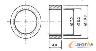
Figure 1: Schematic diagram of plastic internal gear size
Since the plastic internal gear is wrapped on the core by shrinkage after injection molding, and the molded plastic internal gear has a large number of teeth, the required release force is relatively large. In addition, because the wall thickness of the tooth root of the small modulus plastic internal gear is only 0.9mm, if the pusher is used for the plastic part to be ejected, the diameter of the push rod should be about 0.5mm, which makes the top part of the plastic part bear the top. If the pressure is too large, it is very likely that the plastic parts will be worn over, causing damage to the plastic parts and failure to release the mold. Therefore, it is necessary to use a push tube or a push plate for ejection. If the push tube is used for ejection, not only the axial dimension of the core is too large, but also the positioning accuracy of the push tube is very high. Based on the above analysis, the author chose to use the push plate to push out the plastic parts.
Polyoxymethylene (POM) has the characteristics of high strength, fatigue resistance, creep resistance and dimensional stability. It is an ideal plastic gear material, so POM is used for injection molding of small modulus plastic internal gears.
Second, the analysis of mold design points
2.1 Gating system design
Moldflow is a professional injection molding CAE software with powerful analysis capabilities, which is widely used in the optimization design analysis of injection molding. When designing an injection mold for a small modulus plastic internal gear, the author first used Moldflow software for optimal gate position analysis. The surface mesh (Fusion) can reduce the computer operation time while ensuring the analysis accuracy, so the grid type selects Fusion. The average side length of the grid is set to 0.2 mm depending on the local minimum size of the plastic part. The software analysis results show that the gate should be placed on the inside or outside of the middle height of the plastic part. I chose to place the latent gate on the outside of the middle of the plastic part, as shown in Figure 2, because the gate is placed here without affecting the normal use of the plastic internal gear.
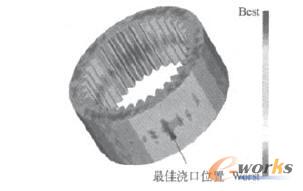
Figure 2: Optimal gate location analysis results
The size of the latent gate should not be too large, otherwise the flow path and the plastic part are not easy to be disconnected, which in turn affects the normal demolding of the flow channel aggregate and the plastic part. The size of the gate is 0.6mm. For a one-cavity cavity arrangement, the overall design of the gating system is shown in Figure 3.
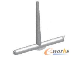
Figure 3: Schematic diagram of the gating system
2.2 Molding component design
The molding assembly is shown in Figure 4. The tooth profile of the small modulus plastic internal gear is formed by a small modulus metal outer gear core 3. The core has a height of 4 mm, a tooth top thickness of 0.07 mm, and a cogging width of 0.16 mm. Due to the small tooth shape, the core cannot be processed by gear cutters; and because the height of the core exceeds 1 mm, it cannot be processed by photolithography resin and electroformed metal; the suitable processing method is WEDM. First, the mold alloy steel billet is ground to a plate of the required thickness, and then a small modulus metal external gear is cut from the plate using a 0.1 mm molybdenum wire on a numerical control wire cutting machine to obtain a desired core. A 2.5 mm standard ram is used as the core fixing rod, and a thread is formed on the rod portion to cooperate with the nut of the M2.5 to fix the core to the upper end of the movable mold insert 5.
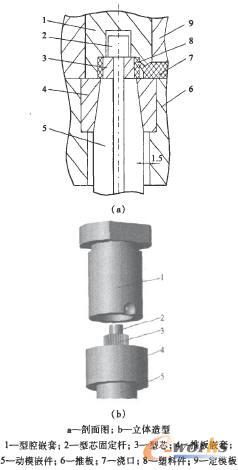
Figure 4: Schematic diagram of the molded component
In order to facilitate adjustment and replacement, the push plate is nested in the portion of the push plate that is in contact with the movable mold insert. A tapered surface is used between the nesting of the push plate and the insert of the movable mold, so that no scratching occurs during the clamping, thereby reducing wear and improving the service life of the mold. The push plate nesting is fixed in the push plate by the interference fit. In order to facilitate the nesting of the push plate when the mold is repaired, the big end radius of the inner tapered hole of the push plate is smaller than the movable mold insert on the push plate. The mounting via radius is 1.5mm.
The cavity nesting for forming the shape of the small modulus plastic internal gear is placed on the side of the fixed mold. When the moving and fixed molds are separated, the plastic internal gears wrapped around the core due to the contraction are first removed from the fixed mold cavity, the plastic parts are left on the side of the movable mold, and then the push plate pushes the plastic parts out of the core. .
The latent gate is placed on the cavity nest. In order to ensure that the flow path portion on the cavity nesting is accurately engaged with the flow path portion on the fixed template, the cavity nesting needs to design an anti-rotation structure. The structure is disposed on the head of the cavity nested and is not disposed on the rod portion (as shown in FIG. 4b), which is beneficial to the processing of the cavity nesting anti-rotation structure, and is also suitable for the mounting type on the fixed template. The processing of the matching holes of the cavity nesting rod portion improves the processability of the machining.
2.3 Mold overall structural design
The overall structure of the mold is shown in Figure 5. The push plate is connected to the reset lever by screws. When the plunger of the injection molding machine pushes the push rod fixing plate of the mold to move forward, the push rod is driven by the reset rod to realize the ejection movement of the plastic part. Since the cold material hole is arranged on the push plate, if the pull rod is still fixed on the push rod mounting plate as in the conventional design, there will be no relative movement between the pull rod and the push plate, and the flow channel aggregate cannot be separated. Pull rod. To this end, the pulling rod is fixed on the moving plate, and the pushing plate forcibly pushes out the flow channel aggregate from the pulling rod while pushing out the plastic piece. In order to facilitate removal of the flow slag adhering to the push plate, the cold pocket on the push plate is designed as a shallow spherical recess.
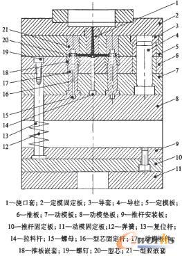
Figure 5: Overall structure of the mold
Figure 6 shows the mold opening action of the mold. When the injection molding machine performs the mold opening action, the spring on the reset rod causes the push plate to abut against the movable platen, so the mold is separated between the fixed plate and the push plate, and the movable part including the push plate moves with the injection molding machine. The mold mounting plate moves backward. The injection molded small modulus plastic internal gear is removed from the fixed mold cavity by being wrapped on the movable mold core, the latent gate is pulled off, and the plastic part is left on the movable mold side; under the action of the pulling rod, The latent gate and the main channel are also removed from the fixed part and left on the side of the movable mold. When the injection molding machine performs the ejection action, the injection molding machine top rod drives the push plate to move forward through the reset rod, and the plastic parts and the flow channel aggregate are respectively removed from the core and the pull rod. After the plunger of the injection molding machine is withdrawn, under the action of the spring, the reset lever drives the push plate to reset first, and then the mold is closed to the next working cycle.
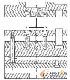
Figure 6: Schematic diagram of the mold opening action
Third, injection molding test
The injection molding material was selected from POM of Japan's Polyplastics Co., Ltd. under the designation M9044. The injection molding equipment is a 12A micro injection molding machine from Germany BOY Company. Due to the narrow molding temperature range of the POM, the injection speed is fast and the mold temperature needs to be increased. The injection molding process parameters used by the author are shown in Figure 7.
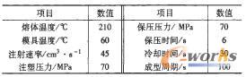
Figure 7: Injection molding process parameters
During the injection molding process, the mold runs smoothly, and the plastic parts and the flow channel aggregate are smoothly released. The injection molded small modulus plastic internal gear plastic parts are shown in Fig. 8. After inspection, the appearance of the plastic parts and the internal tooth shape are well formed and meet the design requirements.
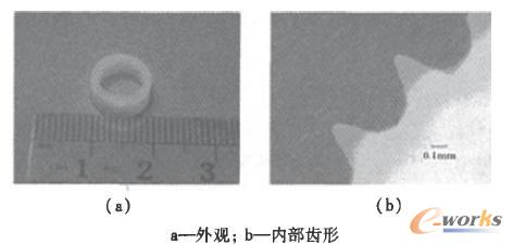
Figure 8: Injection molded small modulus plastic internal gear plastic parts
Fourth, the conclusion
By analyzing the structure and injection molding characteristics of small modulus plastic internal gears, based on the analysis results of Moldflow software, the injection molding scheme of latent gate and pusher plate ejection was designed. The cavity assembly is compact and reliable. The formed small modulus plastic internal gear has good appearance and internal tooth shape, meets the requirements of use, and can provide reference for the mold design of similar plastic gear products.
For more information, call 18824561887, Peng, Emill: [email protected], QQ. Website: http://. Welcome friends from all walks of life come to visit, guide and negotiate business.
Http://news.chinawj.com.cn Editor: (Hardware Business Network Information Center) http://news.chinawj.com.cn
Polycrystalline Silicon,Mono Solar Panels,Polycrystalline Silicon Solar Cells,Mono Solar Cell
ZHONGWEI CITY YINYANG NEW ENERGY , https://www.yinyangnewenergy.com