As a way of supplying energy, the multiple advantages of electric power means that the use of electricity is almost limitless. For example, mass transit, heating, lighting, telecommunications, computing, etc. must all use electricity as the main source of energy. In the power transmission control sector, there is something called a high and low voltage distribution cabinet, which has a very important role. The following Xiao Bian will take you together to understand the high and low voltage distribution cabinets.
First, the basic introduction of high and low voltage distribution cabinet
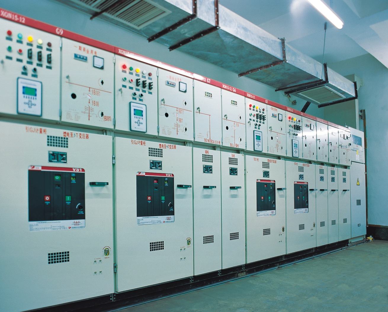
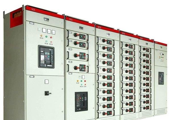
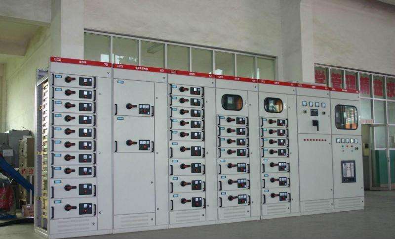
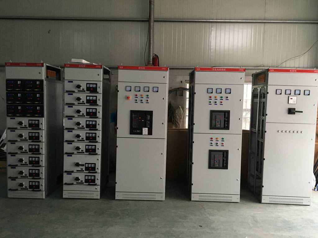
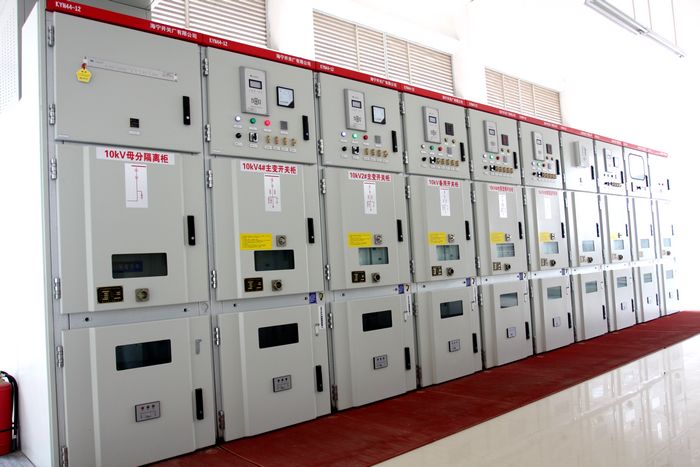
As the name suggests, high and low voltage distribution cabinets are power distribution equipment used for power distribution, control, metering, and connecting cables in power supply systems. The general power supply bureaus and substations use high-voltage switchgears and then transformers step-down low-voltage side. Leading to low-voltage power distribution cabinets, the low-voltage power distribution cabinets are used to protect power distribution boards, control boxes, and switch boxes, which are protected by devices such as switches, circuit breakers, fuses, buttons, indicator lights, meters, and wires. Devices that are assembled into a single distribution device that meets the design function requirements. Commonly known as: high and low voltage switchgear or high and low voltage electrical equipment.
Second, the choice of power distribution room high and low voltage distribution cabinet
1, low voltage distribution cabinet selection
(1) Select the main technology of low-voltage power distribution cabinet and specify the detailed technical parameters
Low-voltage power distribution cabinets generally choose to master the basic parameters first, such as rated voltage (rated insulation voltage AC 660V, rated operating voltage AC 380V), rated frequency 50Hz, rated current (generally not exceeding 4000A) and the area occupied by the cabinet size. The most important concern is the upper limit of the nominal current through which the vertical bus and horizontal bus pass, the rated peak withstand current and rated short-time withstand current range, the functional unit segmentation capability, the external enclosure protection class, and the motor capacity control. These must meet basic standards, otherwise it will affect the stability and safety of low-voltage distribution cabinets.
(2) Mastering important originals in low voltage distribution cabinets
From two aspects of analysis, on the one hand is to meet the general requirements. The cabinet has a lightweight design, a variety of mounting templates, easy assembly of the assembly, functional classification, modularized installation dimensions, and the upper limit of operation of the temperature environment. On the other hand is the circuit breaker application. Circuit breakers not only have various interlocks for selection and step-by-step protection, such as interlocking between cabinet doors and switches and cabinet doors, cascade protection for pre-stage backup protection, etc., but also various functions such as memory function, access, and The line can be freely changed direction, high segmentation ability, three protection functions, accident warning, alarm functions. It also requires that all relevant accessories and configuration functions be modularized.
2, high voltage distribution cabinet selection
(1) Reliability selection of high voltage distribution cabinet
The reliability of power supply refers to the features of easy replacement, easy operation, convenient maintenance and safety, and it can be completely realized that the combined components extracted from the handcart cabinet are installed on independent cars. The use of handcart cabinets has increased the requirements for construction and requires the improvement of the car. For the transformation inside the cabinet, balance should be achieved inside and outside the cabinet. The top surface of the rail inside the cabinet and the floor outside the cabinet are two parallel surfaces, which is the entry and exit switch cabinet of the trolley. Provides convenience; the middle cabinet is an upgrade of the trolley cabinet, and its advantage lies in that an independent trolley can be used to install and replace the combined components in the central cabinet of the cabinet, and the professional carrier equipment is removed; the fixed cabinet is applied early. One of the cabinets has a fixed internal structure. Compared with the advanced cabinet type, it has a longer power outage time and is more difficult to repair. It has a lower power supply continuity and lower reliability. Therefore, the project capital investment, reliability analysis of power supply equipment and other factors have become the focus of consideration.
(2) Practical selection of high voltage distribution cabinet
Domestic and imported high-voltage power distribution cabinets have the same proportion in the market, and the selection of the advantages and disadvantages of these two types of high-voltage power distribution cabinets should be based on the actual needs of specific needs. First, select the size of the product according to the distribution room space. If the area is sufficient, choose domestic equipment to provide a reasonable price, convenient customer service, and reliability;
If the area is relatively narrow, choose imported products, compact design, compact size, but the price is more expensive, there are many problems after-sales service. What is particularly emphasized is that with the innovation and development of China's scientific and technological revolution, the quality and reliability of equipment can be guaranteed. Therefore, the selection of high-voltage power distribution cabinets as the primary fulfillment condition is practical, and then the selection is made based on actual needs.
(3) Simple selection of high voltage distribution cabinet
Complex configurations are more prone to problems, so simplification is the future direction of development of high-voltage power distribution cabinets. Therefore, the newly developed integrated intelligent protector type is currently the best cabinet type to reduce these problems. This type of cabinet construction is simpler than the previous ones. It simplifies the construction of the unit in the cabinet, has a low warranty rate, and saves manpower and material resources. Therefore, under the conditions of adequate investment, a new type of intelligent, integrated high-voltage power distribution cabinet is a good choice, not only shorten the working time, but also can simplify the complexity of things, catch up with the pace of development of the times.
Third, high and low voltage distribution cabinet installation specification
1, check the preparation before installation
Before installation, the supervision engineers and the engineers of Party A shall check whether the approach roads are unimpeded. If necessary, they shall require the general contractor units to build simple transportation corridors to connect with the installation points. The construction site layout shall meet the requirements for safe and civilized construction. At the same time, it is also necessary to check the arrangement of the construction equipment of the installation unit and urge the installation unit to inspect the construction equipment to ensure a good condition. Before the high-voltage equipment arrives at the site, the power distribution room, trenches and foundation channels should be completely completed.
1) Distribution room
Distribution room: Before the construction of the power distribution room, the detailed drawings needed to build the distribution room shall be submitted to the construction party (within two weeks after signing the contract, the customer shall confirm the position, content and completion time of the drawings), and During the construction of the power distribution room, technical personnel of our company or the cooperative unit must supervise on site to avoid construction errors. (It will take about 2 weeks to build the power distribution room)
2) Foundation: The location of the channel steel should correspond to the equipment air duct reserved in the power distribution room. The minimum distance from the equipment to the wall should be clear (the distance is too close and the door of the equipment cannot be opened). (The welding of the channel steel takes about 2 days, our technical staff must be on site to guide)
The equipment arrived at the scene:
3) If the power distribution room and foundation are not built, the equipment should have a storage location (to prevent rain or provide necessary rainproof materials).
2, installation
2.1 The doors and windows of each power distribution room shall be tight and the room shall be clean.
2.2 The switchboard is firmly installed. The connection between the equipment inside the pan and the components is firm.
2.3 The grounding of the panel and cabinet should be solid and good. Openable discs and cabinet doors equipped with electrical appliances should be reliably connected with flexible wires and grounded metal structures.
2.4 Terminal box installation should be firm and well closed. The installation position should be easy to check. When installing the terminal box, it should be arranged neatly.
2.5 The cabling inside the distribution board should be horizontal and vertical, the screws should not be loose, and the thread heads should be in good contact.
2.6 The components inside the plate are fixed and reliable without looseness, and the contacts are free from oxidation and burrs.
2.7 The connectors of the secondary circuit should be made of copper products.
Specific requirements for the connection:
2.7.1 The connection of the electrical circuit (bolt connection, plugging, welding, etc.) should be solid and reliable.
2.7.2 The cable cores and the ends of the conductors to which they are fitted shall be marked with their loop number;
The number should be correct, handwriting clear and not easy to decolorize.
2.7.3 The wiring is neat, clear and beautiful; the wires are well insulated and free of damage.
2.7.4 There shall be no joints in the wires in the pan and cabinet.
2.7.5 The wiring on each side of each terminal board is generally one and shall not exceed two.
2.8 When the secondary circuit of the 400V or less secondary circuit is between the live body or between the live body and the ground, the electrical clearance shall not be less than 4mm. Leakage distance should not be less than 6 mm.
2.9 The wires used to connect the movable parts (on-board appliances, console boards, etc.) should meet the following requirements:
2.9.1 should use a plurality of flexible wire, laying should have appropriate redundancy.
2.9.2 The wiring harness should have reinforced insulation (such as plastic jackets, etc.).
2.9.3 When connecting with an electrical appliance, the ends shall be tightly closed and must not be loosened or broken.
2.9.4 Apply clips at both ends of the movable part.
2.10 The control cables and their cores introduced into the panel and cabinet shall meet the following requirements:
2.10.1 Cables for the introduction of trays and cabinets shall be arranged neatly to avoid crossover and shall be securely fastened so that the terminal strips to which they are attached are not mechanically stressed.
2.10.2 The strip of armored cable shall not enter the plate or the cabinet; the end of the armored steel strip shall be tightly closed;
2.10.3 For control cables for transistor protection, control and other logic circuits, when shielded cables are used, the shields shall be grounded; if not, shielded cores shall have a ground.
2.10.4 rubber insulated core wire should be sheathed with insulating tube protection;
2.10.5 The cable cores in the trays and cabinets shall be regularly or vertically arranged, and shall not be randomly connected diagonally; the spare cores shall be left with an appropriate degree of redundancy.
2.11 In places where insulated conductors may be subject to oil corrosion, use oil-resistant insulated conductors or take oil-repellent measures.
2.12 Safety Technical Requirements for Distribution Devices:
2.12.1 When two or more power sources are supplied, interlocking devices shall be installed between the main power supply and the tie switch of each power source (except the dispatcher of the power supply department).
2.12.2 The interlocking device shall be installed between the disconnector and the corresponding circuit breaker of the 10 kV indoor equipment.
2.12.3 The phase arrangement of the distribution equipment should meet the requirements of the column:
(1) The alignment of the circuits in the same distribution device should be as consistent as possible.
(2) The hard bus bar should be painted. The colors are: a phase yellow; b phase green; c phase red; neutral black.
(3) The soft bus should be marked with phase.
(4) The wires in the interval of the power distribution device shall be left in the position where the temporary grounding wire is suspended. The paint should not be applied here.
2.13 Terminal board installation should meet the following requirements:
2.13.1 The terminal board shall be non-damaged, securely fastened, and well insulated.
2.13.2 The terminal board should be easy to replace and easy to connect.
2.13.3 For circuit voltages exceeding 400 volts, the terminal block shall be sufficiently insulated and marked with a red mark.
3, check
3.1 Inspection
3.1.1 The ventilation, lighting and safety fire protection devices of the high and low voltage distribution room are normal.
3.1.2 The switchboard door is strictly non-destructive. The switchboard is clean and dust-free.
3.1.3 All distribution panels in the station must be listed as a warning.
3.1.4 The signal lights, bells, accident clocks, etc. of the signal device circuit shall be accurate and reliable.
3.1.5 The voltage and current of the motor in the distribution cabinet are normal (not exceeding 5% of the rated value).
3.1.6 Is there any overheating phenomenon in the busbars and the contacts? Is the temperature indicating wax melting and the insulating bakelite burned?
3.1.7 The electrical components in the switchgear have abnormal odors and sounds during operation.
3.1.8 Is the oil level of the oiling equipment normal? Does the oil color become dark and there is no oil leakage?
3.1.9 Whether the indication of the instrument, signal, indicator, etc. is correct or not, and the position of the relay protection platen is correct.
3.1.10 Is the relay and DC equipment running well?
3.1.11 Are there any loose and broken wires in the connection line between the grounding and the zero-connecting device?
3.1.12 Is the insulation of porcelain vases, insulation bushings, and wall bushings clean and free from broken cracks and discharge marks?
3.1.13 Is the mechanical interlock of circuit breaker and disconnecting switch flexible and reliable? If electromagnetic interlocking device is used, it shall be electrified to check whether the electromagnetic lock action is flexible and whether the opening and closing is accurate.
3.2 monthly inspection
A comprehensive inspection of each operating and electrical part of the motor and distribution cabinet, a magnetic starter dynamic closing test, and a relay sensitivity test are performed every month.
3.3 years inspection
Every three years, a relay test is performed on the motor and the distribution cabinet, which is verified by the power supply personnel.
3.4 Inspection and Maintenance
3.4.1 Inspection and maintenance are performed once a month.
3.4.1 Power-off maintenance lines must be listed first and then operated as a warning.
3.4.2 The motor, cable and power distribution screen must be well grounded, and the grounding resistance should not be greater than 4 Euro.
3.4.3 The motor measures the DC impedance for the AC voltage withstand test. Current transformers and voltage transformers are used for pressure tests and current ratio tests.
3.4.5 The cable is used for DC voltage leakage test; the relay is overhauled and reset.
3.4.6 oil switch for dismantling check repair, adjustment, fastening; arrester for pressure test.
The above is the relevant information about high and low voltage distribution cabinets . Have you got a certain understanding after reading? More home improvement knowledge, please pay attention to this site information!
Monitoring equipment Swimming pool equipment Low voltage distribution box Cleaning equipment
The Reinforcement Net have a wide scope of application as reinforce the production of industrial farics, mixed laminar , plasticand / or paper composites and for the structural sppport of polyurethane seats for cars, trains and planes, bed mattress, water filter and air filter.
The Plastic Net is made of Polyethylene (PE), polypropylene (PP), has the clear advantage of being ladder-proof and maintain high dimensional stability throughout the extruded bioriented production process.


Reinforcement Net
woven reinforcement net, plastic reinforcement net , Reinforcement Mesh, Anti-Crack Reinforcement Mesh
Hebei TongChan Imp.&Exp.Co., Ltd. , https://www.tongchanmesh.com