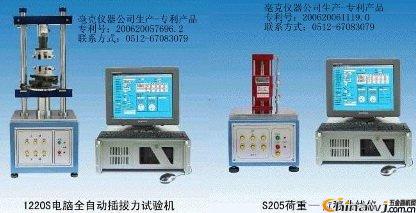
Example of the Insertion Force Tester Test
The 1220SA plug-in force tester is not only capable of measuring the insertion force of connectors, but also supports multiple functions such as: break force testing, constant tensile stress testing, impedance testing, single pin retention test, and positive force testing. Below are detailed instructions on how to operate this device effectively.
**1. Insertion Force Test**
- First, set the movement mode to "two-way measurement" with a speed range of 1~300 (standard machine speed). You can adjust the number of tests from 1 to 10,000,000.
- Ensure that the start position is properly set and check the origin before beginning.
- Insert the male and female connectors of the tested product into the clamps. Make sure the clamps are vertical and the automatic centering device is positioned near the center to avoid misalignment or damage.
- Zero the load and press the move button on the panel to separate the male and female ends slightly, without fully removing them. Monitor the display for movement.
- Set the test stroke to be slightly less than the actual stroke, around 0.1~0.2mm.
- After setting all parameters, click “File†and “Pre-set Storage†to save the file. The file name should only contain letters, numbers, periods, and hyphens—no spaces allowed.
- Begin the test on the screen.
- If the stroke cannot be found, use a height gauge to measure the insertion stroke of the male plug. Adjust the position of the connectors accordingly, ensuring the stroke does not exceed the actual measured value. The starting position is equally important.
**2. Break Force Test**
- Clamp the test product into either the upper or lower clamp, and adjust the height so it is securely held.
- Set the mode to "Break Test" and configure the stroke based on the actual length of the product, allowing it to be fully pulled out.
- Set the speed and number of cycles, then save the file.
- Return to zero and clamp the product again. Note: Do not return to zero after clamping.
- Start the test on the screen.
**3. Pin Retention Test**
- Connect the sensor interface to the test rod and lower the fixture, adjusting the position appropriately.
- Set the load measurement range to be greater than the force required to remove the pin. The stroke measurement range should be smaller than the stroke above the insulation surface of the pin to avoid missing the actual force reading.
- Select “Load Zero Position (only when force starts counting)†and each time the origin is detected, save the settings.
- Perform the test.
- Alternatively, you can use the “Single Direction Measurement†mode, which will show a black return force curve in the graph.
**4. Constant Tension and Tensile Stress Test**
- Choose the constant tension mode, and the software will automatically open the “Force†and “Time†data frames. Enter the desired force and time values, then save the file.
- Clamp the test product and adjust its position accordingly.
- Start the test. When the set force is reached, the timer begins, and the test completes once the time is up.
- For constant pull tests, the process is similar, except there is no return stroke.
- Note: These tests tend to be slower, typically around 30 mm/min.
**5. Longitudinal Force Test**
- Select the load zero position, and make sure the origin is detected each time. Choose the unit as “gram.â€
- Attach the appropriate test rod to the test head.
- Adjust the position and test the corresponding stress value for the stroke.
- Some customers may require the stress value at the bottom point of the stroke. In such cases, contact the after-sales technician for assistance.
**6. Load-Displacement Test**
- When you want to measure the deformation stroke under a specific force or the force at a certain displacement, follow these steps:
- Set the load measurement range to the required force value and ensure the stroke range is large enough.
- Select the load zero position and detect the origin each time.
- Set the speed (typically around 30 mm/min), number of tests, and save the file.
- Run the test and observe the waveform. The imax value represents the stroke you need to measure.
**7. Contact Resistance Test**
- Set the parameters according to the normal insertion force test.
- In the last column of the measurement items, select “Insertion Point Resistance Value.â€
- Clamp the male and female connectors using the impedance test fixture.
Additional extended tests, such as anti-bending tests, peel force tests, shrapnel switch displacement load tests, constant tensile life tests, and break force measurements, can also be performed using the 1220SA model. For more details, please contact the manufacturer directly. Note: These procedures apply specifically to the 1220SA model with a patent certificate.
Editor: Hardware Business Network Information Center | http://news.chinawj.com.cn
Hotel Outdoor Furniture
Hotel or resort outdoor furniture should be able to bear harsh weather conditions. Usually, aluminium and rattan are considered the best materials for outdoor furniture.
Aluminum material known as a sturdy, weather resistant and enduring material and can be custom made any design.
Our PE rattan wicker materials are 100% recyclable and are non-toxic, which can be wicked into any shape.
Hotop provides all kinds of outdoor furniture for hotel and resorts.
Rattan Hotel Outdoor Furniture,Commercial Patio Furniture,Hotel Outdoor Dining And Pool Furniture,Resort Furniture And Chairs,Commercial Pool Furniture
Guangzhou Hotop Hotel Supplies Co.,Ltd , https://www.hotopsupply.com