introduction
In the manufacture of aerospace products, aircraft assembly is the process of combining parts and components (components, components) according to design and technical requirements to form a high-level assembly or complete machine. Due to the large size, complex shape, and the large number of parts and connectors, the aircraft assembly accounts for about half or more of the total labor of the aircraft. Therefore, developed countries in Europe and America are very concerned about aircraft assembly technology and have invested heavily in research and development. .
At present, the flexible assembly technology that is booming at home and abroad is an advanced assembly technology that can adapt to rapid development and production and low-cost manufacturing requirements, and modular and reconfigurable equipment and tooling. It combines with digital technology and information technology to form a new field of automated assembly technology.
1 wing box assembly process
1.1 Introduction to Aircraft Wing Box Assembly
In the wing structure, the portion of the middle section of the rib and the spar and skin is called a wing box. The wing box is the main load-bearing structure of the wing. The wing box is not only the main wing structure that keeps the aircraft flying, but also the work of the aircraft fuel tank. Each aircraft has two wing boxes that fit on the left and right wings. The wing box bears most of the weight and pressure during the takeoff, cruising and landing of the aircraft. The aircraft wing also supports the aircraft's powerplant and main landing gear.
The traditional aircraft wing box assembly adopts vertical assembly, that is, the front frame of the aircraft is fixedly suspended in the vertical plane by the frame, the ribs are installed perpendicular to the front beam, the rear beam of the wing box is installed, and the skin is finally installed. ,As shown in Figure 1.
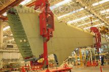
Figure 1 Vertical assembly of wing boxes
1.2 shortcomings of vertical assembly
Traditional vertical assembly requires the sling to be suspended in the air, requiring a large amount of space. For large aircraft, such as the Airbus A380, the assembly frame is up to tens of thousands and takes up too much space.
The vertical wing is not in working condition and its parameters are not well measured and evaluated. For example, in vertical assembly, the space heights of the front spar and the rear spar are up to ten or even tens of meters, and there is a certain temperature difference, and the difference in temperature causes different deformation of the parts, which brings precision errors to the assembly.
The horizontal assembly method is to place the wing box horizontally on the fixture for assembly operation, which can solve the above problem. The horizontal assembly technique is to solve the problem of flexible design and how to perform assembly operations.
2 wing box horizontal assembly flexible fixture design
2.1 Flexible frame based on box connection technology
The box connection, as shown in Figure 2, is a combination of a series of standard beams and connectors that combine. The joints in the device, without welding or other permanent connections, use a frictional joint of bolted connections. The advantage of the box connection concept is that it consists of standard modular components made of steel or carbon fiber. The modularity of the system can be adapted to different sizes of assembly. Another advantage is that it does not need to be as precisely configured as a conventional device, as the entire device can be adjusted at any time. The main frame based on the box connection technology is shown in Figure 3.
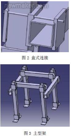
In this paper, the size data of the main frame composed of square beam and box connection is: the length of the beam is designed to be 1.5m, and the interface size of the beam is designed to be 140mm x 140mm x 6mm. The vertical beam is the same size as the beam. The size of the intermediate plate is 190mm x 190mm, and the area of ​​contact with the beam is 140mm x 140mm.
The depth of the groove is designed to be 10 mm. The force analysis of the two side plates is similar to that of the intermediate plate, and the size is the same as that of the intermediate plate. Only one side is slotted, and the depth of the groove is 10 mm.
2.2 Flexible positioning device based on hexapod positioning
In the flexible holding part before the frame and the aircraft wing box, a six-legged positioning device is used to meet its flexibility requirements. The hexapod positioning device is shown in Figure 4.
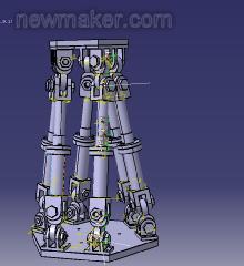
Figure 4 hexapod positioning device
The hexapod positioning device bottom plate is mounted on the frame by a box connection, and the top plate is connected to the wing box to be held. The movement of the top plate is achieved by connecting the six legs of the top plate and the base. In fact, the top plate can be moved to any position within any angle of its working space by arbitrarily changing the length of the leg. An important feature of the hexapod positioning device is that the top plate has a corresponding length setting of six legs in any position of the space. When the hexapod positioning device is reset, this connection can be easily adjusted to reach a new position.
2.3 Auxiliary facilities for horizontal flexible assembly
In the vertical assembly process, the assembly operation is mainly performed on the side. For horizontal and horizontal assembly, the assembly operation needs to be performed above the wing box due to the horizontal placement of the wing box. In this way, it is necessary to additionally establish a type of frame with a lifting platform, and place the robot above the wing box to be assembled to perform various operations in the assembly process of the wing box. In addition, there is a form for fixing measuring devices such as industrial cameras, and performing the necessary measurement work during the assembly of the frame and the assembly of the wing box.
A complete flexible clamp formed by the main frame, the hexapod positioning device, and the robot positioning mechanism and measuring device is shown in FIG.
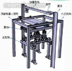
Figure 5 The composition of the overall fixture
3 wing box horizontal assembly flexible fixture verification
3.1 Component Stress Analysis
The main frame needs to bear a weight of 500Kg and the material is carbon structural steel of grade Q255. Since the load-bearing weight of each beam is not uniform during the assembly process, and the assembly operation may have a slight impact, it is assumed that the beam is subjected to a weight of 600 kg. The beam model is fixed at both ends, and a downward concentrated load of 5886N is applied at the centroid position. The CATIA finite element analysis module is used to analyze the beam, as shown in Fig. 6. The calculated maximum stress is 8.05 MPa and the maximum deformation is 0.044 mm.
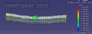
Figure 6 Finite element analysis results of the beam
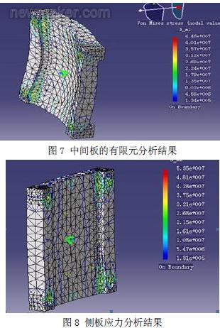
The finite element analysis is carried out on the intermediate plate of the box connection. The four bolt holes are fixed in position, and a concentrated force of 10960N is applied at the centroid position of the surface in contact with the beam. The analysis result is shown in Fig. 7, and the maximum stress of the intermediate plate is 44.6. MPa, occurs at the location of the four holes.
The finite element analysis was performed on the side plates of the box connection, the four screw holes of the side plates were fixed, and a concentrated load of 10906 N was applied on the side in contact with the beam. The maximum stress is 53.5 MPa. The maximum displacement is 0.0158 mm, as shown in Figure 8.
After analysis, the maximum stress on each component does not exceed the allowable profit range of the material, and the displacement caused by the strain can be adjusted by the hexapod positioning device so that it does not affect the assembly accuracy.
3.2 Motion Simulation
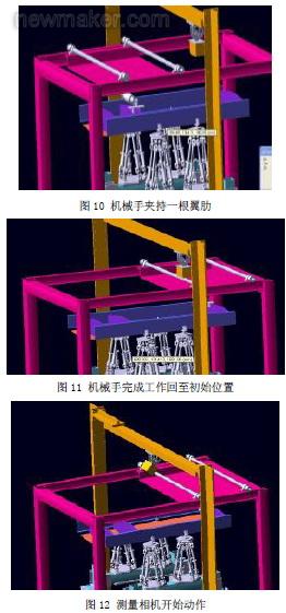
Motion simulation can simply show the working process of the flexible fixture, which is an important part of the entire fixture verification work. Due to the limited simulation function of CATIA's own digital prototype module, this paper uses the interface software simdesigner to import the assembly model in CATIA into ADAMS. The final simulation implementation is based on CATIA+SimDesigner+ADAMS. Figure 9-12 shows the main simulation results, in which Figure 9 is the initial position, Figure 10 is the robot holding a rib and mounting it on the spar in the correct position, Figure 11 is the robot to complete the work, by the top robot frame The belt is returned to the initial position, and Figure 12 shows the start of the camera mounted on the measuring frame, measuring the gap between the rib and the panel assembly.
The simulation results show that the fixture can achieve the expected working process.
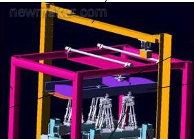
Figure 9 initial position
3.3 Measurement aid verification
For the measurement work of horizontally assembled flexible fixtures, depending on its characteristics, there are some special measurements during the installation process and during the assembly of the wing box. During the installation process, not only the position of the frame beam is measured by the laser tracker, but also the adjustment of the position of the connection portion of the box connection is performed, so that the assembly position is within the tolerance range. For the position of the wing box assembly that needs to be assembled, it is also necessary to continuously measure and adjust the hexapod positioning device to determine the accurate assembly position of the wing box. In the course of work, due to the flexibility of the fixture system, the deformation, deflection, displacement and other problems that may occur in the frame and the clamping part, as well as the positional changes caused by changes in environmental factors, must be measured in real time. Adjust the flexible clamping section to meet assembly tolerances.
4 Conclusions and prospects
Flexible fixture technology is an important research direction of aircraft assembly process, and the horizontal assembly method of wing box has good development prospects due to its high precision and convenient operation. In this paper, a research and design verification study of a miniature flexible fixture for horizontal assembly of aircraft wing boxes is carried out. The future research focuses on the empirical application of horizontally assembled flexible fixtures for wing boxes and how to implement modular design and control of flexible fixtures through software to achieve efficiency and cost savings.
References References
[1] Guo Enming. Flexible assembly technology for foreign aircraft [M]. Aviation Manufacturing Technology, 2005 (9), 28-32.
[2] Fan Yuqing. Modern Aircraft Manufacturing Technology [M]. Beijing: Beijing University of Aeronautics and Astronautics Press, 2001.
[3] Alison millar, Henrik Kihlman. Reconfigurable Flexible Tooling for Aerospace Wing Assembly [J]. SAE international, 2009.
[4] Zou Yuhua, Liu Zhicun, Fan Yuqing. Research on Digital Docking Assembly Technology for Large Aircraft Parts. Computer Integrated Manufacturing System. 2007(7), 1367-1372
[5] Qiu Hongjun. Research on Key Technology of Aircraft Assembly Process Design Based on Knowledge
[D]. Northwestern Polytechnical University, 2006.

Concerned about surprises
Tag: flexible design frame assembly accuracy assembly process motion simulation
Previous: Stirring titanium alloy/aluminum alloy dissimilar metal friction stir welder Next: Application and advantages of aluminum alloy cable in engineering
Double Hole Faucet,Double Hook Faucet,Brushed Double Hole Faucet,Single Handle Double Hole Faucet
Jiangmen Faer Sanitary Co.,Ltd , https://www.faersanitarys.com